|
|

|
Medical Devices of the Neck & Spine...neck apparatus
by Tim B Hunter, MD, MSc and Mihra S Taljanovic, MD, PhD
Neck Apparatus
Gastric and Tracheal Tubes
Many medical devices travel through the neck en route to thoracic and abdominal structures
(Price, 1991; Stoelting, 1986; Hunter, 2001). Endotracheal tubes, tracheostomy tubes, orogastric tubes, nasogastric tubes, oral
airways, and feeding tubes are common findings on cervical spine and chest radiographs (figure: DCS, nasogastric tube and ET tube; figure: nasotracheal and orogastric tubes; figure: esophageal temperature probe). Because these tubes start from similar locations and go through neighboring structures, it is often difficult to differentiate between tracheal and gastric tubes, especially on bedside chest radiographs. Both may be placed through the nose, and they overlap in size and appearance. Small tubes, however—especially those less than 5 mm in diameter—are usually feeding tubes. Endotracheal and nasogastric tubes are composed of radiolucent materials, but the manufacturers usually add a barium stripe or other high-density stripe to make the tube easily visible on radiographs.
Even so, it may still be hard to differentiate an endotracheal tube from a nasogastric tube. Endotracheal tubes can be more easily recognized on lateral views because they lie anterior to gastric tubes and within the airway. They often can be identified if they are seen to pass between the vocal cords. Endotracheal tubes, orogastric tubes, and oral airways are placed through the mouth. They are much less common than nasogastric tubes, which are placed through the nose. Oral airways are made of rubber or plastic, but they are usually reasonably opaque, and they can be recognized at times by their location and their H or oval shape in cross section. They are placed only for a short-term or emergency intubation.
Most of the time, endotracheal intubation is lifesaving. Unfortunately, it can also be life threatening if the tube is not in the proper position. The location of the endotracheal tube tip should always
be ascertained. When the neck of an adult is in a neutral position, the tip of the tube should be
approximately 5 cm above the tracheal carina at about the level of the aortic knob. In children,
depending on their size, the tube tip should be 2–5 cm above the tracheal carina. In general, the
tracheal carina is just distal to the level of the aortic arch. If the tip of the endotracheal tube is just above the aortic knob, it is in good position, midway between the vocal cords and the carina. This position allows safe excursion of 2 cm upward or downward when the patient flexes or extends the neck. Tubes tend to descend when the neck is flexed and ascend when it is extended.
If the endotracheal tube has a cuff, the balloon should not be inflated to more than one and a half times the diameter of the trachea. Prolonged overextension of the endotracheal cuff can lead to ischemic necrosis of the tracheal cartilage and tracheomalacia.
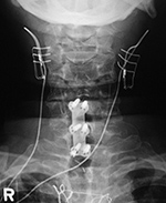
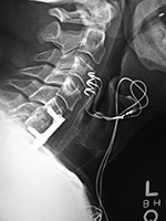
Tracheostomy tubes are composed of dense plastic or metal and are readily visible on most images (figure: tracheostomy tube). In an ideal situation, they are placed by an experienced surgeon for a patient who requires prolonged respiratory therapy or to provide an airway for a patient who has suffered grievous injury to the upper airway, neck, or face. Tracheostomy tubes are usually inserted between the second and third tracheal rings. They can be placed emergently, but in some emergency situations, a cricothyroid tube is used instead. Cricothyroid tubes are easier and quicker to insert than tracheostomy tubes, but they carry a higher risk of vocal cord damage. They may be difficult to distinguish from a tracheostomy tube unless one is provided with an adequate history of a cricothyroid tube insertion.
Back to Top
Vagus Nerve Stimulator
Vagus nerve stimulation is an experimental technique for controlling seizures in patients for
whom drugs and surgery have been ineffective (Morris, 1999; Rosenbaum, 2000; Terra, 2014). A vagus nerve stimulator consists of a small electrode, which is implanted around the left vagus nerve in the left side of the neck (figure: vagus nerve stimulator). The electrode is connected to a programmable generator, which is placed under the skin in the upper left side of the chest. Left vagus nerve stimulation is thought to have little effect on the heart, whereas right vagus nerve stimulation produces more cardiac effect.
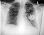
Experimental work has shown that stimulating the vagus nerve innervates a number of organs, including the heart, lungs, larynx, vocal cord, stomach, tongue, and ears, and it sends sensory signals into the brain stem. For unknown reasons, such stimulation may control seizures, and it has also been shown experimentally to be successful in treating depression (Ogbonnaya, 2013). It may also have a therapeutic effect in treating chronic syncope (figure: bilateral vagus nerve stimulators).
Lumboperitoneal Shunt
Communicating hydrocephalus (non-obstructive hydrocephalus) is usually treated with a ventriculoperitoneal shunt or, occasionally, a ventriculoatrial shunt. Another less frequently used option is the lumboperitoneal shunt (Li, 2001; Burgett, 1997; Bloch, 2012) (figure: lumboperitoneal shunt). Because it does not require a transcranial approach, a lumboperitoneal shunt is potentially safer for the patient. A programmable shunt that will allow valve pressure settings to be periodically adjusted can be used. The shunt may be laparoscopically placed at the midlumbar level with drainage of the spinal subarachnoid space into the peritoneal cavity. Lumboperitoneal shunts are sometimes used to treat pseudotumor cerebri and other nonspecific conditions. They tend to fail more commonly than ventriculoperitoneal shunts, and they have all the usual potential complications associated with shunts, such as infection, migration, tubing disconnection, hemorrhage, and chronic pain.
Temperature and Oxygen-sensing Probes
Accurate measurement of body temperature and oxygenation is an important part of patient care,
especially for patients undergoing extensive surgery; those suffering from hypothermia, hyperthermia, or heat stroke; and those in profound shock from trauma or sepsis (Vicenzi, 2000; Mekjavic, 1990; Robinson, 1998). There is a variety of temperature monitoring devices including axillary temperature patches, esophageal temperature probes, temperature probes incorporated in urinary catheters, electronic thermistors inserted into the pulmonary artery, and rectal temperature probes.
The choice of the probe type depends on the patient’s condition and the experience of the patient’s physicians. Esophageal and nasopharyngeal temperature probes may be seen in operative or immediate postoperative patients (figure: esophageal temperature probe). These probes are commonly placed through the mouth and may be evident on neck and cervical spine images. The tip of the probe sometimes lies in the oropharynx or the proximal esophagus. The probes come in various designs, and some can monitor electrocardiographic tracings, heart rate, core body temperature, aortic flow waveforms, and oximetry. The proper placement of an esophageal or nasopharyngeal probe is subject to much discussion. Some advocate that the probes be placed in the retrocardiac portion of the esophagus where they are less influenced by the exchange of gases in the mouth and upper airway. Others believe it is easier to place the probes in the neck because retrocardiac placement is more difficult to perform accurately.
Back to Top
Medical Apparatus in the Neck
| Dorsal column stimulator (DCS), nasogastric tube, and endotracheal tube |
Nasotracheal and orgogastric tubes |
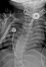
Tracheostomy tube AP view |
Tracheostomy tube lateral view |
 |
 |
 |
 |
| Lateral radiograph of the neck shows a recently placed dorsal column stimulator, a nasogastric tube (black *), and an endotracheal tube (white *). |
The nasotracheal tube is larger and anterior. The orogastric tube is smaller and posterior (arrow). From |
AP and lateral views show incorrect placement of a tracheostomy tube. The tip of the tube is to the left of the trachea on the AP chest view and anterior to the airway (arrow) on the lateral neck view. From Hunter, 1994 |
 |
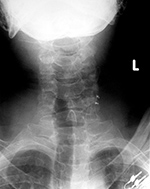
| Vagus nerve stimulator |
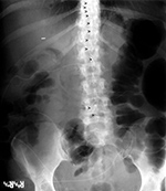
Lumboperitoneal shunt |
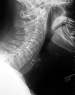
Esophageal temperature probe |
 |
 |
 |
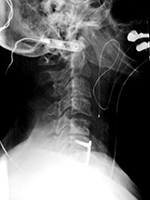 |
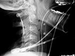
| A left vagus nerve stimulator was placed to treat intractable epilepsy. |
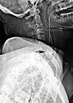
45 year-old woman with two lumboperitoneal shunts to treat pseudotumor cerebri. The inferior shunt tip is at the L4-5 level (lower arrowheads). The superior shunt (upper arrowheads) goes into the thoracic region with its tip not pictured. From Hunter, 2004 |
There is also a pulse oximater probe on one of the earlobes, an endotracheal tube, and an anterior cervical fusion plate. From Hunter, 2004 |
|
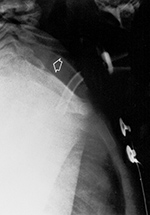
| Vagus nerve stimulator |
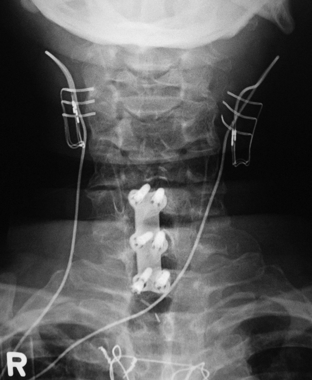
Bilateral vagus nerve stimulators |
|
 |
 |
 |
|
| Same patient as above. The battery pack (generator) for the stimulator overlies the left chest with stimulator lead (arrows) going into the left side of the neck. |
62 year-old man with anterior cervical fusion plate and screws C5-7 for treatment of prior cervical spine trauma. Bilateral vagus nerve stimulators were placed to treat chronic syncope. |
|
Back to Top
|