Neck & Spine
|
|
|
Thoracic and Lumbar Spine |
|
|
|

|
Medical Devices of the Neck and Spine continued
by Tim B Hunter, MD, MSc and Mihra S Taljanovic, MD, PhD
Thoracic and Lumbar Spine Instrumentation
Spinal Implants
Thoracic and lumbar implant surgery is performed to correct severe congenital or developmental spinal deformities or defects. It is also used to stabilize the spine and repair damage to bone and ligaments resulting from trauma, typically motor vehicle accidents, gunshot wounds, and diving accidents. The main congenital disease indications are severe scoliosis, kyphosis in Scheuermann disease, spinal stenosis, and spinal dysraphism (Cotrel, 1988; Drummond, 1988; Egnatchik, 1990; Luque, 1986; Selby, 1982; Steffee,1986; Hu, 1992; Slone, 1993; Aebi, 1998; An, 1999; Benzel, 2012; Hitchon, 1995; Ha, 2014).
Posterior Spinal Instrumentation
Posterior spinal instrumentation is preferred over anterior spinal instrumentation in the thoracic and lumbar regions, because it allows easier decompression
and visualization of neural elements. The posterior surgical approach is much simpler and safer in general than an anterior approach going through the neck, chest, or abdomen. On the
other hand, the anterior approach is generally preferred for spinal surgery in the cervical region
for two reasons. First, posterior instrumentation in the cervical spine is usually limited, because the vertebrae in the cervical spine are smaller, as is the volume of the soft tissue. Second, the substantial implants used posteriorly in the thoracic and lumbar regions are too large to be used in the cervical spine. Mechanically, they would not safely fit in the cervical region, and the degree of support they provide for the thoracic and lumbar regions is not needed in the cervical spine.
Surgery to fuse the lumbar spine has been performed for more than 100 years. The techniques used for the earliest procedures involved only bone grafting in situ, and they are still applicable today. Currently, it is quite common to combine bone grafting with the use of spinal fixation apparatus to improve fusion rates. Successful bone grafts are necessary for the ultimate success of spinal surgery. If the bone grafting and eventual fusion are not successful, the spinal fixation apparatus will ultimately fail. Spinal implants are very useful, however, for they often permit less extensive surgery, providing immediate spine stability, improved fusion rates, and rapid patient mobilization and rehabilitation.
One of the first practical applications of spinal
fixation apparatus was the use by Luque of sublaminar wires attached to anchor rods for thoracic
and lumbar spine posterior stabilization (figure: Luque rods). Although this technique provided very secure
fixation, it had a relatively high risk of associated neurological complications. In Luque’s original
technique, the wires were “blindly” passed under the lamina at surgery with no direct visualization of the spinal dura neurological elements. The original technique has for the most part been replaced with use of segmental wires passed through the base of the spinous processes. The new technique is easier for the surgeon, and it avoids injury to the spinal cord and its nerve roots.
In a further modification of the original sublaminar wire technique, rectangular fixation devices (Luque and Hartshill rectangles) (figure: Hartshill rectangle) or metallic buttons (figure: Wisconsin posterior spinal wiring) are used with sublaminar wires designed to hold the metallic rectangles or buttons to adjacent vertebrae. Harrington rods (flanged ends) and Knodt rods (threaded rods) have hooks along the rods (figure: Harrington rods). They are designed to either distract the spine or compress it, depending on the direction in which the hooks are placed. The distraction or compression is used to treat a variety of congenital and developmental deformities, such as marked adolescent scoliosis. Sometimes, the deformity is stabilized so that it will not worsen as the patient grows older. Sometimes, the deformity can actually be partially corrected. This type of apparatus may also be used to secure the spine after the collapse of a vertebra from trauma, infection, or tumor.
Thoracolumbar stabilization rods have a long record of success and are among the most commonly used spinal stabilization apparatus. They do have the disadvantage of their sublaminar hooks, which can compress the thecal sac or directly harm the neural roots or even the spinal cord. In the lumbar spine, they also tend to cause a loss of the normal lumbar lordosis (the so-called flat-back syndrome), which may produce disabling chronic pain over time. Pedicle fixation systems were designed to overcome these problems. In these fixation systems, screws are placed through the pedicles into the vertebral bodies. The screws are connected together on each side, with rods or a plate placed over the pedicle screws on each side. There are many variations on this common design, with several systems now available, including the Steffee, Edwards, Roy Camille, and Cotrell-Dubousett devices (figure: lumbar pedicle screws and rods; figure: Brantigan intervertebral cage; figure: Steffee plates and screws; figure T12-L2 pedicle screws and rods).
The Steffee design is very common. It uses flat plates to connect
the screws, whereas the Cotrell devices use rods to connect to the screws. The TiMx Comprehensive Low Back System is a titanium system composed of pedicle screws, spine plates, washers, rods, slotted connectors, and a cross connector (figure: posterior spinal fusion). Most of these systems are combined with posterolateral “bony fusion masses” (osseous grafts) composed of bone pieces or bone shavings taken from the iliac crest tuberosity on one or both sides. The bony fusion masses are packed around the fixation devices, and in 4–5 months they evolve to become solid masses of mature bone. The fusion of bone provides the ultimate stability for the spine. If fusion is not successful, the fixation apparatus often eventually fails, with breakage or loosening of components.
Back to Top
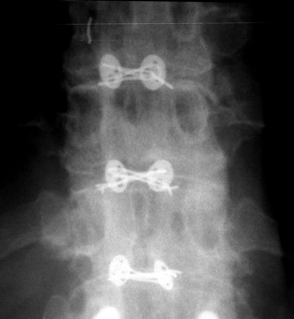
| Bilateral Luque rods |
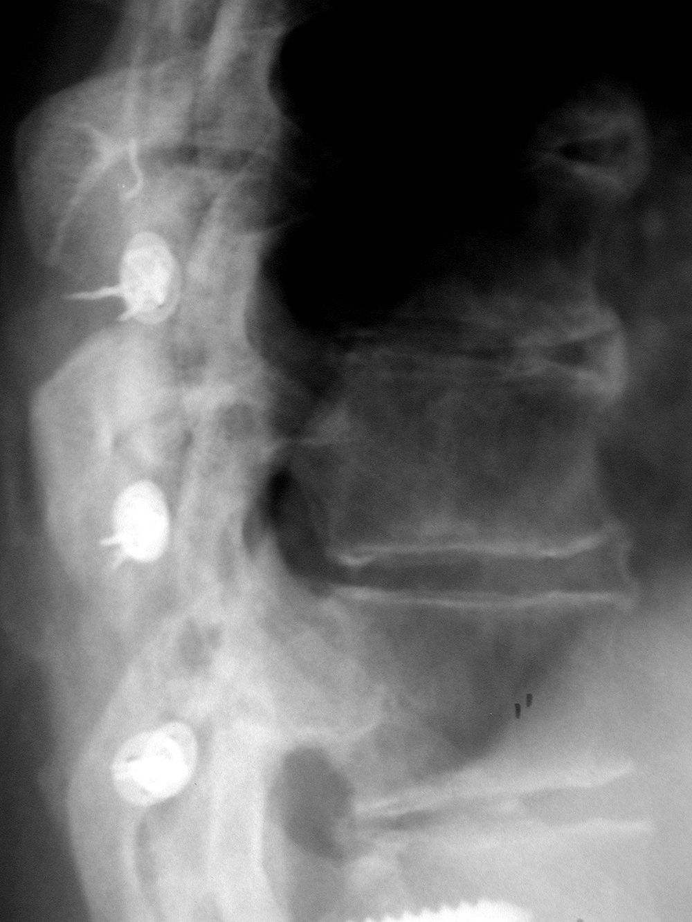
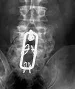
Hartshill rectangle |
Wisconsin posterior spinal wiring: AP view |
 |
 |
 |
 |
| There are bilateral Luque rods for treatment of scoliosis. The rods are fractured at the T12 level. |
Hartshill rectangle used to treat degenerative disease in the lower lumbar spine. There is surrounding bone fusion. The wires through the sacral lamina are broken which is not a problem with the solid bony fusion. From Yoshino, 1994 |
The wires go under the lamina and are connected to buttons that sit external to posterior elements of the spine. From Hunter, 2004 |
 |
| Wisconsin posterior spinal wiring: lateral view |
Harrington rods |
Brantigan interbody vertebral cage |
 |
 |
 |
 |
| The wires go under the lamina and are connected to buttons that sit external to posterior elements of the spine. From Hunter, 2004 |
The hooks on these rods are designed for distraction. From Hunter, 2004 |
Harrington rods are at the thoracolumbar junction stabilizing a vertebral body fracture. The hooks (thick arrows) anchor the rods in the lamina. Segmental wires around the lamina (thin arrow) supplement the fixation. From Benjamin, 1994 |
In the lower right hand corner of the cage there is a small metallic rod for radiographic identification. The cage is composed of high density carbon fiber with grooves for bone incorporation into the vertebrae. From Yoshino, 1994 |
|
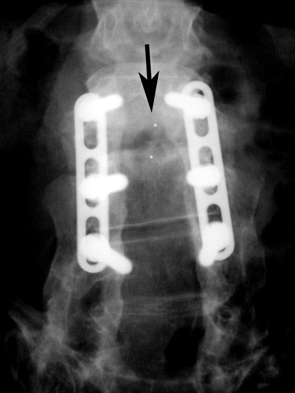
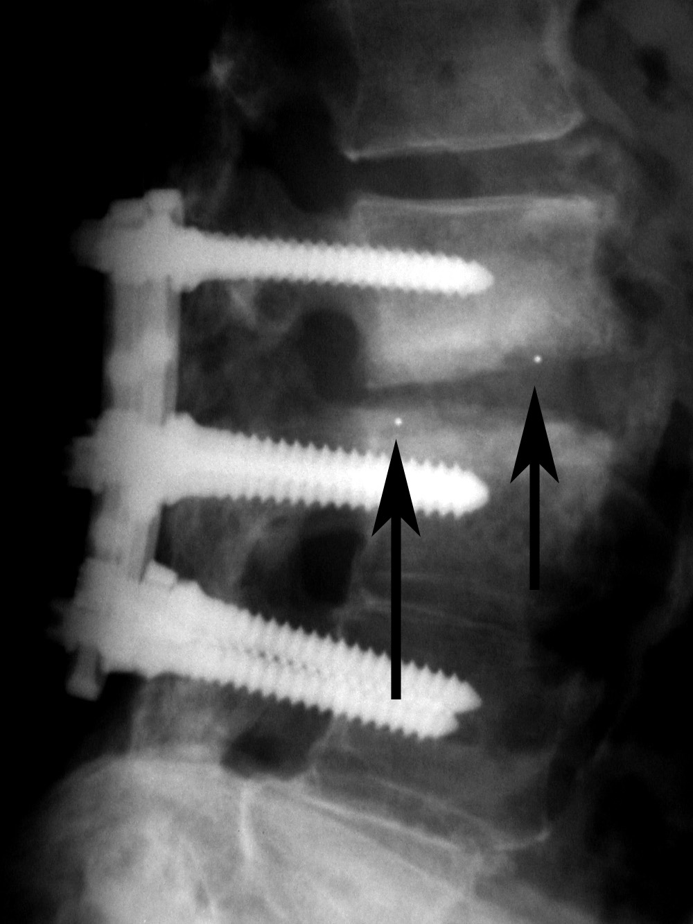
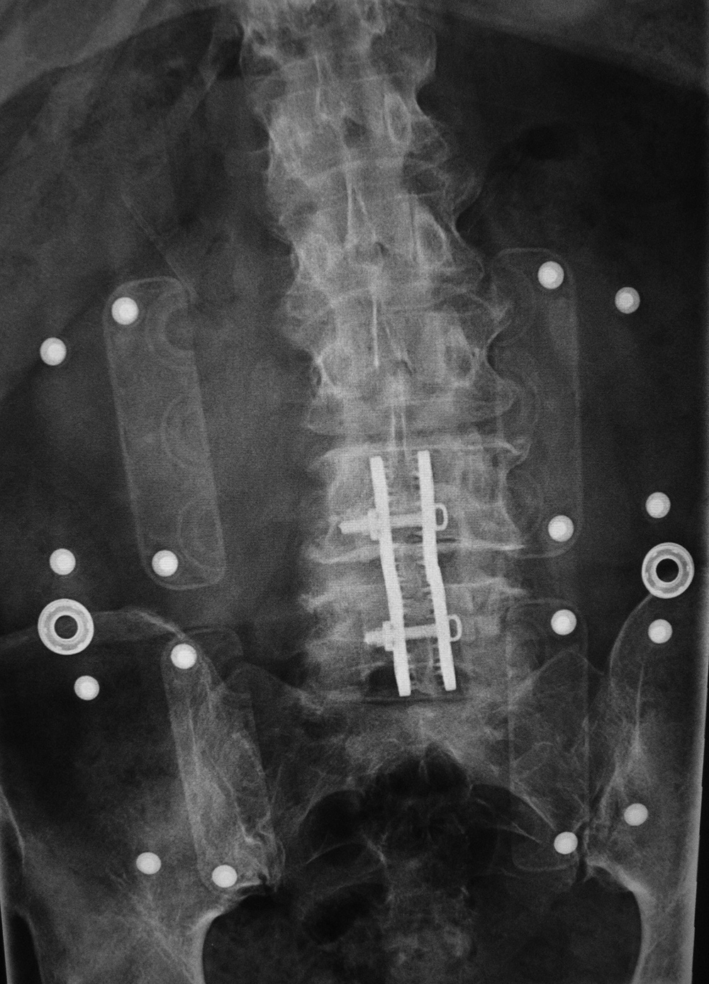
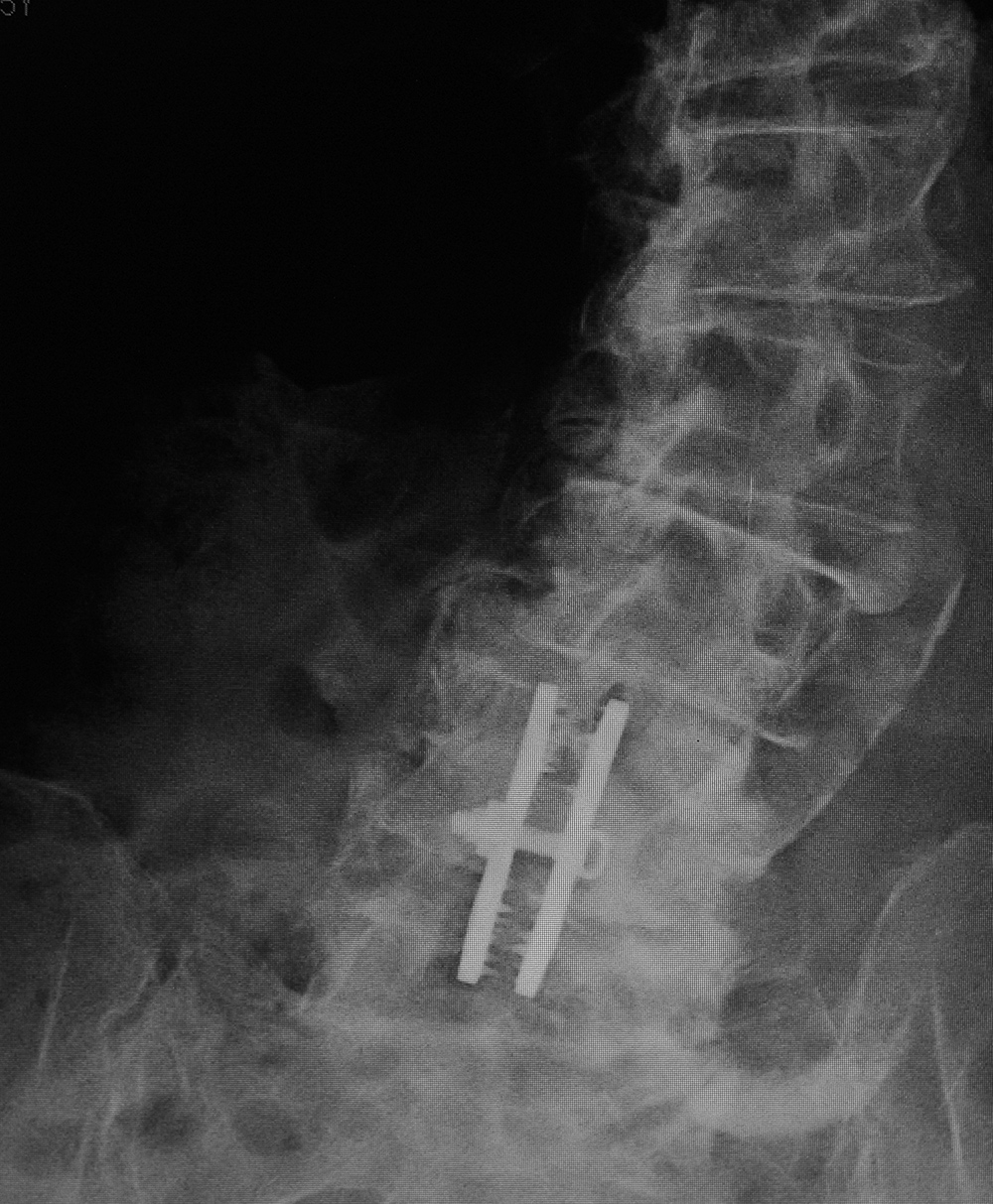
| Steffee pedicle plates and screws |
Posterior spinal fusion apparatus |
 |
 |
 |
 |
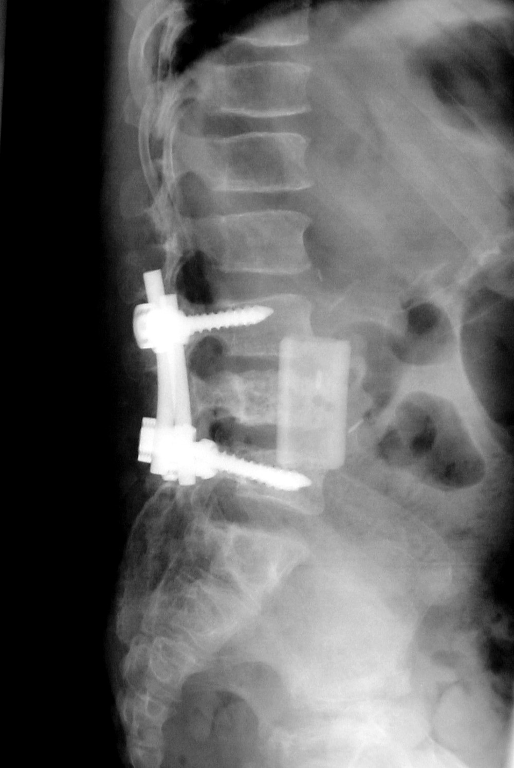
| Frontal and lateral views in two different patients show bilateral Steffee plates and screws in the lumbar spine with two side by side Brantigan intervertebral cages (arrows) at L2-3. |
Shown are pedicle screws and rods on each side, two crosslinks (at L4 and S1), and intervertebral disk spacers at L4-5. |
|
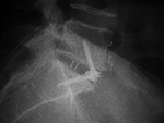
| Anterior lumbar interbody fusion (ALIF) |
Anterior lumbar interbody fusion (ALIF) |
 |
 |
 |
 |
| 47 year-old woman with anterior lumbar interbody fusion (ALIF) at L5-S1. |
60 year-old man with L5-S1 anterior diskectomy and interbody fusion with zero-profile fixation screws at L5-S1. There are PEEK interbody disk grafts at multiple levels from ALIF prior surgery at L2-3 to L4-5. |
|
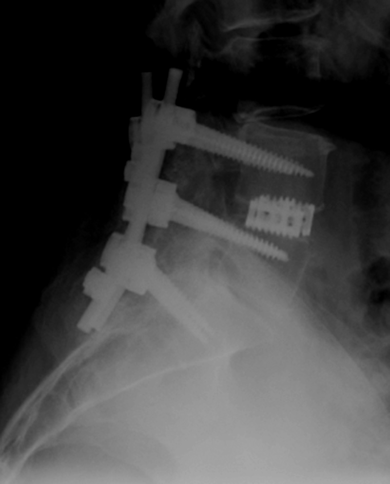
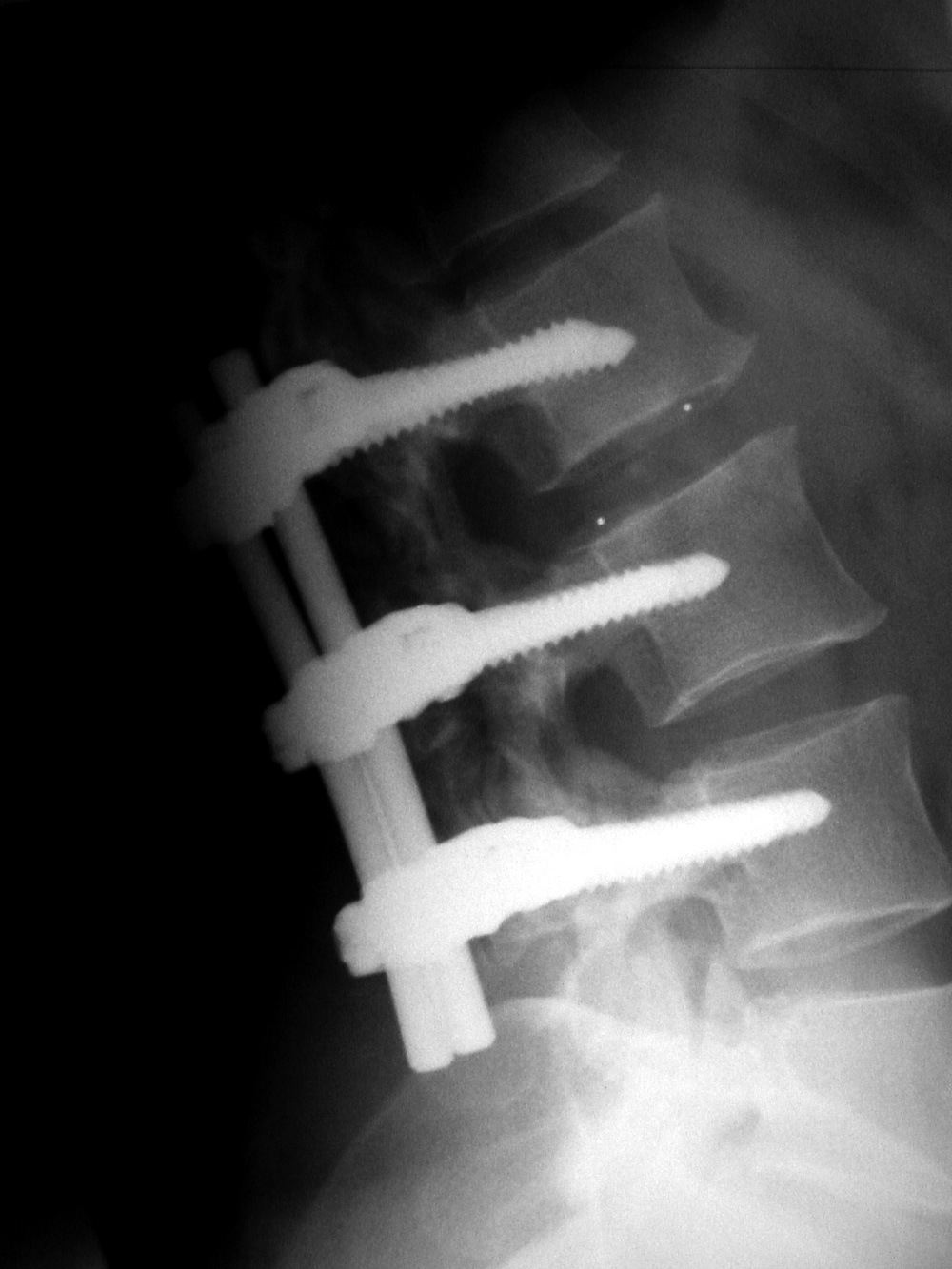
| Pedicle fixation screws and rods |
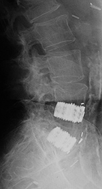
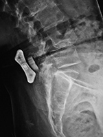
Lumbar spine disk spacers at L4-5 and L5-S1 |
 |
 |
 |
 |
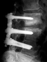
| 20 year-old woman with L1 vertebral body compression fracture treated with T12-L2 posterior spinal fusion using pedicle screws at T12 and L2 with connecting rods on each side. |
59 year-old woman with past history of spinal surgery. |
Back to Top
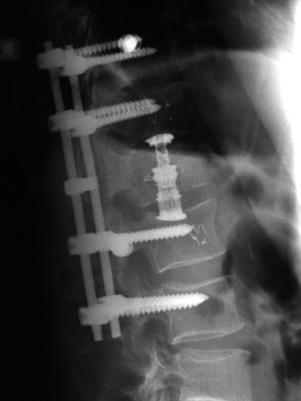
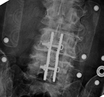
| Extensive lumbar spine fusion with pedicle screws and rods |
ILIF: Interlaminar lumbar instrument fusion |
 |
 |
 |
 |
| A laminectomy has been performed from T12-L5. Pedicle screws and rods are at L3-S1 from the initial lower lumbar spine fusion. Later surgery added pedicle screws and rods at T12-L3, and L3-L5 with a crosslink at L2. |
67 year-old woman with L3-4-5 ILIF. There are partial laminectomies at L3 and L4. Posterior L3-5 stabilization is obtained with a spinous process clamp. There is also posterior L3-5 arthrodesis using structural allograft. The patient is wearing a TLSO brace. |
|
| ILIF: Interlaminar lumbar instrument fusion |
 |
 |
 |
 |
| 85 year-old woman. These images show respectively an AP radiograph of an ILIF at L4-5, an axial CT image of the ILIF, and two coronal reformatted CT images of the ILIF. There is a donar bone plug held in place by the interspinous fixation plate (clamp). |
|
| Interspinous clamps (ILIF) at L4-5 |
Interspinous clamps (ILIF) at L4-5 |
 |
 |
 |
 |
| 67 year-old woman with lower lumbar spinal stenosis. The patient is wearing a TLSO brace. |
76 year-old woman treated for degenerative spondylolysthesis at L4-5. The patient is wearing a TLSO brace. |
|
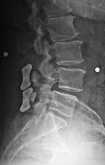
| Lumbar spine bony disk strut, pedicle screws, and pedicle rods (AP view) |
Lumbar spine bony disk strut, pedicle screws, and pedicle rods (lateral view) |
Harms vertebral cage (AP view) |
Harms vertebral cage (lateral view) |
 |
 |
 |
 |
| There is an anterior allograft bone strut used to treat metastatic neuroblastoma in the L4 vertebral body. The bone strut crosses both the pathologic vertebral body as well as its adjacent disk. The anterior position of the bone strut is typical for these struts. From Hunter, 2004 |
There is a vertebral cage and side plate and screws in the lower thoracic spine for treatment of a spinal tumor. |
|
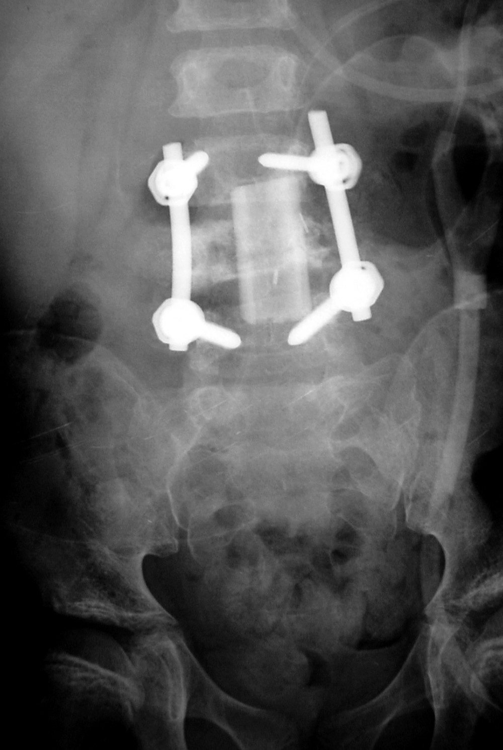
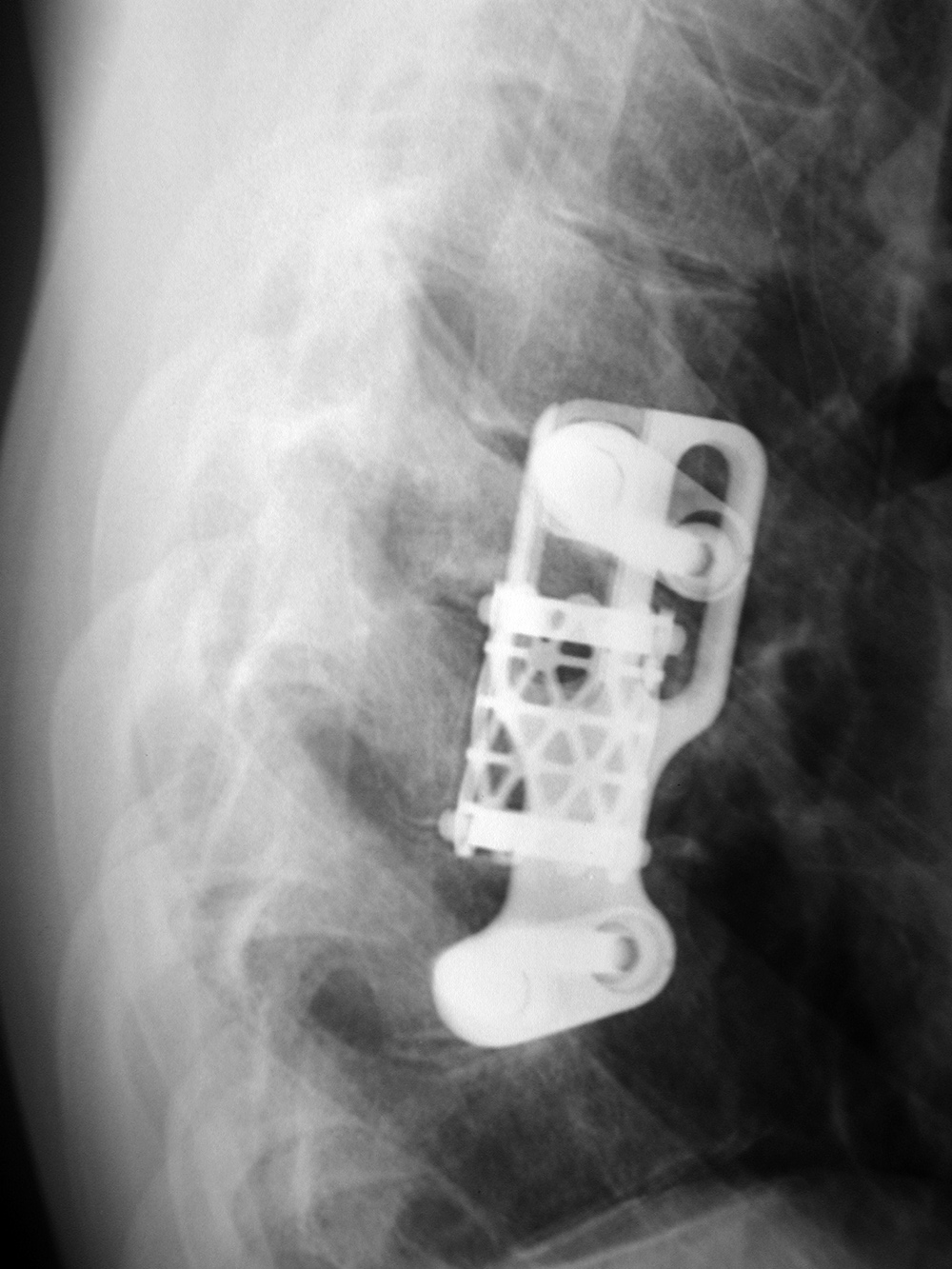
| Vertebral compression fracture treated by expandable corpectomy device |
Interbody vertebral cages |
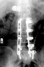
Bone stimulator |
 |
 |
 |
 |
| There are also bilateral pedicle screws and connecting rods above and below the level of the fracture. |
The cages are at L1-2 with bilateral pedicle screws and rods going from L1 to L3 for degenerative lumbar spine disease. |
The battery pack overlies the right 12th rib. Wires are going to the bilateral bony fusion masses. There is a laminectomy from L2 to L5 with bilateral pedicle screws and a pedicle plate on the right and a connecting rod on the left. Brantigan vertebral cages are at the L5-S1 disk space. |
Back to Top
|